

|

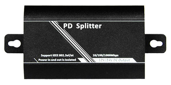
Single channel isolated PoE Splitter

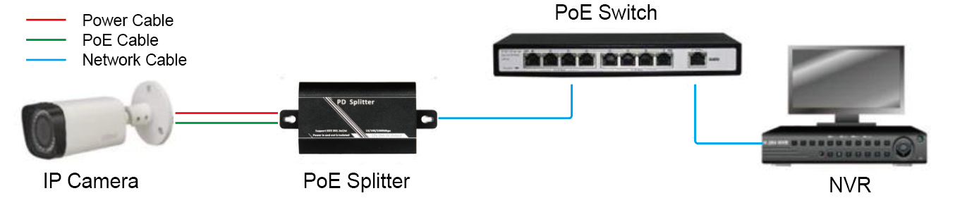
FS-PD2001-GM is a kind of PD Splitter (also called PoE Splitter), supports IEEE802.3af/at standard; supplies power and transmits data to PD devices (such as IP camera); The product uses the transformer for isolation design, which gives you more stable, more secure effects and well-protects the powered products, Bandwidth is 10/100/1000M. Mid-Span (No.4&5and 7&8 cables supply power) and End-Span (No.1&2 and 3&6 cables supply power) connections are well supported. The product has dual power output: 12VDC, 2.0A, and 24VDC, 1.0A. Some HD digital cameras do not have PoE module which leads to the inconvenience and difficulty on installation. However, this device can solve the problem of wiring. Connect PoE switch with PD Splitter, people can realize the power supply and data transmission of IP cameras directly and timely.
1. Cat5e, Cat6, or Cat7 cable
2. RJ-45 connectors
3. Crimping tool
4. Wire stripper or Knife
1) We recommend stripping at least half an inch of the cable to expose the inner wires.
2) Separate the wires within the cable after the network cable jacket has been removed so that they can be put into the RJ-45 connector.
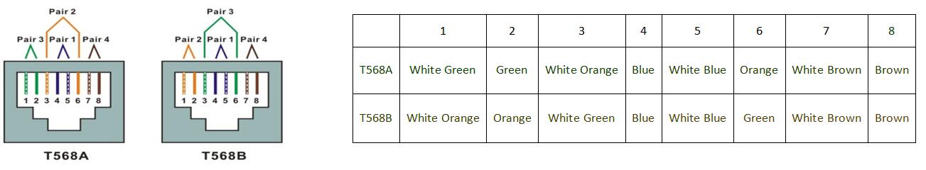
3) The CAT5 twisted-pair cable consists of four twisted wires, each color coded; 8 wires must be correctly lined as the standards of EIA/TIA 568A or EIA/TIA 568B.
4) Cut thread residue and leave 1.5cm wire exposed outside the insulating layer and ensure 8 wires are straighten and neat.
5) Place the cable into the RJ-45 connector and then use the crimping tool to attach the connector.
6) Repeat above steps for the other end of the cable; the wire sequence of both ends of the cable is suggested to be identical.
7) Make sure to test the cables before installing them once both ends of the cable have been completed.
Note:
All RJ-45 Ports of this device support Auto MDI/MDIX, so the different wire sequence of both ends of the cable is allowed.
Installation Steps
Before installation, please check the following equipment and accessories, if there is any missing, please contact with your supplier.
1). 1 pc of FS-PD2001-GM device
2). 1 pc of user manual
3). 1 pc of power line
2. Please install as below steps.
1)Before installation, please turn off the power of all signal sources and the monitor in case of the damage to transmission device.
2)Use network cables to connect PoE power supply device and RJ45 port of PD splitter.
3)Connect DC connectors and RJ45 port with right powered device.
4)Check whether installation is correct or the device is damaged. Before power on PoE device, make sure that all connections are reliable.
Troubleshooting
Such as equipment malfunction, according to the following way.
1)Confirm whether equipment is installed as the manufacturer's installation requirements.
2)Confirm whether RJ45 cable is connected well, make sure no break, whether line order production complies with the EIA/TIA 568A or 568B international standards.
3)Confirm the working power of device is less than PD Splitter’s max output power 12W.
4)Confirm whether PoE device can work normally. Use normal PD device to test if the PoE power supply works.
5)Use a set of normal FS-PD2001-GM device to replace the broken device, which to examine whether the equipment is damaged.
6)If still cannot deal with the troubleshooting, please contact with the manufacturer.
|
Features |
|
|
Standard |
Support IEEE802.3af/at |
|
Power supply mode |
Support Mid-span and End-span |
|
PoE Input Voltage |
37-57V |
|
DC Voltage Output |
12V or 24V |
|
DC Current Output |
2.0A (12V output voltage); 1.0A (24V output voltage) |
|
Output Power |
25.5W |
|
Port and Performance |
|
|
Electrical interface parameters |
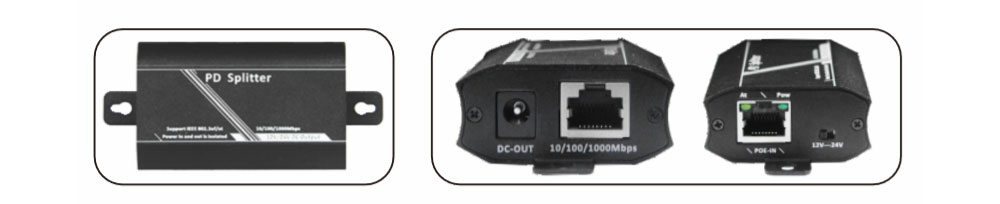
One input RJ45 port One Output RJ45 port One Power supply output DC port |
|
Cable Type |
Cat5 UTP and above |
|
Protocol Standards |
IEEE 802.3i 10BASE-T IEEE 802.3u 100BASE-T IEEE 802.3ab 1000BASE-T IEEE 802.3af/at Power over Ethernet |
|
Bandwidth |
10/100M/1000M |
|
LED indicator lights |
PoE input power supply indicator light IEEE 802.3at PSE detects indicator light |
|
Dimension |
83*51.5*24mm(L*W*H) |
|
Weight (KG) |
99.4g |
|
Environment temperature |
Work temperature:-5~45℃; Work Humidity:90%,No condensation Storage temperature:-20~70℃; Storage humidity:95%,No condensation |
• Security Monitoring System
• Multimedia Network Teaching System
• Medical Monitoring Display System
• Industrial Automation Control System
• Banking, securities, financial information display system
• Remote Network Server Monitoring
• Department Store Security
• Casino Security
• Hospitals, Airports and banks
• School Campuses

Copyright © 2019 Shenzhen Folksafe Technology Co., Ltd. All Rights Reserved | Designed by Joymagic