
|

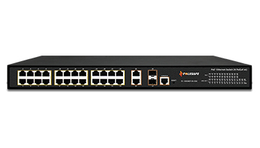
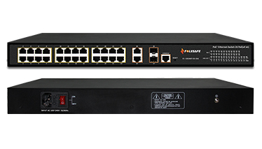
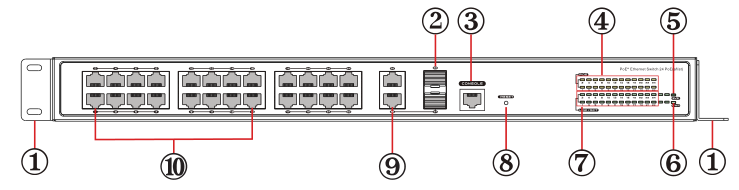
24-Port 10/100Mbps IEEE 802.3af/at Managed PoE Switch (End-Span PSE)
1 Rack-mounting ears: Cabinets for product installation or Wall installation
2 Uplink SFP port: Transfers the data from LAN port to NVR or other switch
3 Console Port: Switch CLI Configuration Interface
4 PoE LED: Yellow. Light on when PD is normal powered, OFF: PD device is not detected or powered
5 System LED: 1 Hz frequency flicker, System operating normally
6 Power LED: Red, Light ON: Normal power supply, Light OFF : No power
7 Switch port LED: Green, Lights when the port is connected, Flashes when is transferring data, OFF: No link
8 RESET Button: Reset the device
9 Uplink GE port: Transfers the data from LAN port to NVR or other switch
10 PoE supply and data transferred port: Supplies the power to PD device and transfers the data
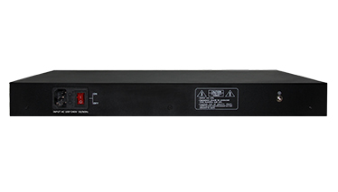
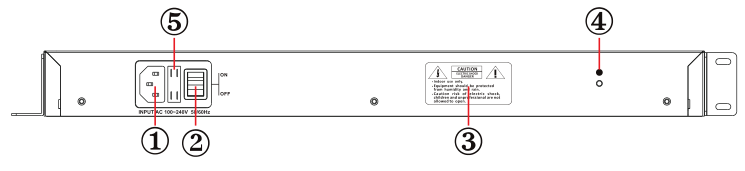
1 Input: AC 100~240V
2 Power Switch: Turn on with power, Turn off no power
3 Warning contents
4 Ground Connection
5 Fuse: Max 10A
1. Cat5e, Cat6, or Cat7 cable
2. RJ-45 connectors
3. Crimping tool
4. Wire stripper or Knife
1) We recommend stripping at least half an inch of the cable to expose the inner wires.
2) Separate the wires within the cable after the network cable jacket has been removed so that they can be put into the RJ-45 connector.
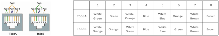
3) The CAT5 twisted-pair cable consists of four twisted wires, each color coded; 8 wires must be correctly lined as the standards of EIA/TIA 568A or EIA/TIA 568B.
4) Cut thread residue and leave 1.5cm wire exposed outside the insulating layer and ensure 8 wires are straighten and neat.
5) Place the cable into the RJ-45 connector and then use the crimping tool to attach the connector.
6) Repeat above steps for the other end of the cable; the wire sequence of both ends of the cable is suggested to be identical.
7) Make sure to test the cables before installing them once both ends of the cable have been completed.
Note:
All RJ-45 Ports of this device support Auto MDI/MDIX, so the different wire sequence of both ends of the cable is allowed.
Package Contents
1) FS-S2024EP-2G-2SG: 1pc 2) AC power cord: 1pc
3) Screw: 10pcs 4) Manual: 1pc
5) Mounting-ears: 2pcs 6) Rubber feet: 4pcs
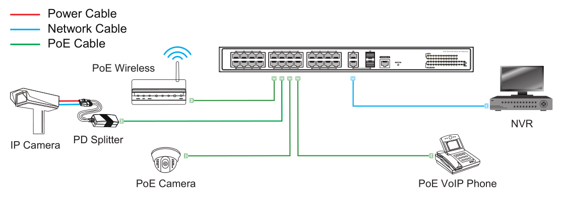
Step 1: Begin with all input/output devices turned off and power cables are removed.
Step 2: Connect RJ-45 port of PoE cameras with Downlink RJ-45 port of PoE switches over standard Cat 5e/6 cables.
Step 3: Connect Uplink port of PoE switches with RJ-45 port of NVR or computer or other devices over standard Cat 5e/6 cables.
Step 4: Connect AC power cord into power socket of PoE switches.
Step 5: Make sure above connection is properly finished, then turn on the power.
|
Model |
FS-S2024EP-2G-2SG |
|
|
Power Supply |
Power Supply Mode |
Built-in Power Supply |
|
Voltage Range |
AC100V~240V |
|
|
Power Consumption |
The device <15W PoE power supply ≤420W |
|
|
Network Port Parameter |
Network Ports |
1~24 Port:10/100Mbps Uplink Port:2x10/100/1000Mbps port and 2x1000Base-X SFP optical fiber port |
|
Transmission Distance |
1~24 port:100m Uplink port:100m; The transmission distance of optical fiber port depends on the different SFP modules |
|
|
Transmission Media |
Downlink Port: Cat5e/6 standard cable Uplink Port: Cat5e/6 standard cable and optical fiber |
|
|
PoE Standards |
IEEE802.3af/at |
|
|
PoE Power Supply Mode |
End-span method |
|
|
PoE Power Supply Wattage |
Each port≤ 30W, Whole device≤420W |
|
|
Network Switch Specification |
Network Standard |
IEEE802.3 10BASE-T、IEEE802.3u 100BASE-TX/FX、IEEE802.3z 、IEEE802.3ab |
|
Swap Mode |
Store-and- forward |
|
|
Data-Caching Mechanism |
8M |
|
|
MAC Address List |
8K |
|
|
Indicator |
Power Indicator |
Red LED on: power on |
|
PoE System Indicator |
1 indicator light (green), Flashing frequency:1s, Steadily on indicates abnormal operation |
|
|
Uplink RJ-45 Port Indicator |
Green light keeps on when is well connected; Blinking when is transferring data |
|
|
PoE Indicator |
24 PoE indicator light (yellow), On indicates PoE power normally, Off indicates no power |
|
|
PoE Network Port Indicator |
1~24 port (green light), keeps on when is well connected; Blinking when is transferring data |
|
|
Button |
Reset Button |
Whole machine will restart while press the button |
|
Protection Level |
窗体顶端 窗体底端 Surge Protection |
6KV(common mode),10/700us IEC61000-4-5 |
|
Electrostatic Protection |
Contact Discharge: ±4KV Air Discharge: ±6KV Standard: IEC61000-4-2 |
|
|
Environmental |
Operating Temperature |
0℃~55℃ |
|
Storage Temperature |
-40℃~70℃ |
|
|
Relative Humidity |
0~95% |
|
|
Mechanical |
Dimensions (L*W*H) |
440mmx297mmx44.5mm |
|
Body Color |
Black |
|
|
Net Weight |
4.5kg |
|
|
Reliability |
Mean time between failures (MTBF) |
>50000h |
• Security Monitoring System
• Multimedia Network Teaching System
• Medical Monitoring Display System
• Industrial Automation Control System
• Banking, securities, financial information display system
• Remote Network Server Monitoring
• Department Store Security
• Casino Security
• Hospitals, Airports and banks
• School Campuses

Copyright © 2019 Shenzhen Folksafe Technology Co., Ltd. All Rights Reserved | Designed by Joymagic